Friday, October 4, 2019

Filter board for Yaesu FT-817, FT-857, FT-897

I published post about making a home made filter board for Yaesu radios and some folks has written me to make the boards for them. Because of that I decided to make more professionally looking PCBs and ordered them in factory.


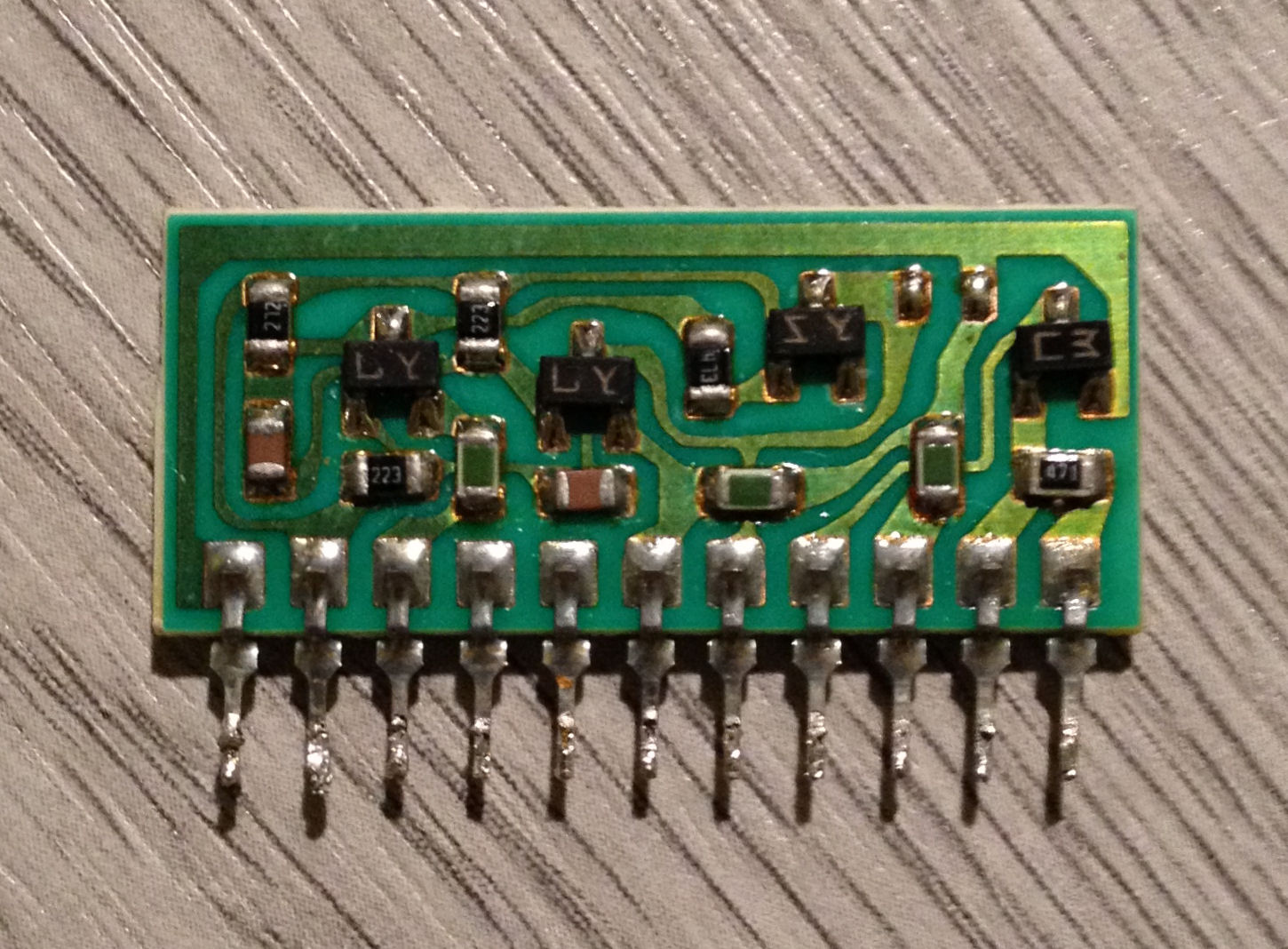
After assembling all the components the filter looks look very professional
Remember to cut excess filter pins sticking out on the bottom side
The filter looks very nice in the radio (FT-817ND)

You can accommodate different filters in the board but you have to pay attention to the coding which is accomplished by soldering zero ohm resistors according to the table below. Radios FT-857, FT-897 use this coding to properly show the filter bandwidth on front display, for FT-817 the coding is irrelevant.


Yaesu Filter Part No
Bandwidth
R1
R5
R6
YF-122CN
300 Hz
-
YF-122C
500 Hz
-
-
YF-122S
2.3 KHz
-
-

If you're interested in purchasing assembled board (without the collins filter itself) please write me.
You can find my email on qrz.com page here.

Thursday, August 2, 2018

Kenwood TR-751 AGC negative voltage problem.

Recently I had to repair friend's Kenwood TR-751. Quick internet query showed that the problem is with negative AGC voltage not being stable. The part responsible for creating the -6V voltage is on separate board and has a symbol X59-1100-00.
X59-1100-00
 The option was to replace the components on that board and capacitors on the main board but this solution was proved to be only temporary as the problem was reoccurring after some time.
The long lasting solution is to build the board using different components.
I have found two versions of the new board. First version is based on LT1054 and described here and second version is based on ICL7660 and is described here.
I decided to build the board around ICL7660 chip because of its lower price and better availability.

Schematic diagram
I changed values of capacitor and resistor to suit my likes and designed new pcb.
New board
Before inserting new module I changed capacitors C135, C136 on the main board to 10uF/25V and also replaced  C137. After repair the voltage measured on the zener diode D90 is about -6,2V and is stable.
The module inserted in place  

Update 2021.12.16
I ordered the boards in factory because there was demand for it. If you need the pcb or complete board please contact me.

Thursday, May 24, 2018

Home made CW YF-122C filter board for Yaesu FT-817/857/897

I purchased Collins mechanical filter XF-115C 500Hz wide which was soldered out of the CW filter for FT-847 and decided to design a board to fit the filter in my Yaesu FT-817ND. The original Yaesu filter board is named YF-122C.
I measured the filter and the dimensions are like on the picture below
Dimensions of XF-115C collins filter
I used KiCad to draw the diagram and the PCB. On the diagram I made holes to put alternative Murata filter and some additional elements like caps (for experiments) which are not necessary to solder.

Diagram schematic of YF-115C/CN/Y filter
 I made the board using laser printer and heat transfer method. You can download the board ready to print (mirror version) here.

PCB of the filter
I made the board with 1mm thick FR4 laminate
Boards are ready, now cutting drilling and soldering.

 The biggest problem was to find the connectors for the board. I couldn't find the original ones at reasonable price in reasonable quantities. After much search I came up with the solution. I purchased some connectors with angled leads and spacing of 2mm like on the picture below and cut them to appropriate size. I purchased them for few dollars here.

2mm pitch connectors
 I cut out the 3pin and 4pin connector, soldered them at an angle and than raised bending them to vertical position so the holes in pcb matched the holes in connector.

Finished filter side by side with original
Bottom side with all elements in place

Filter installed in Yaesu FT-817

 When installed filter works exactly as original YF-122C. Is fully plug and play, no need to solder the filter to the radio's pins like I saw in other DIY work.

Happy CW'ing
Vy 73
Artur

Monday, December 4, 2017

Powering up Remoterig RRC-1258 and FT-857 radio from the same power supply

My antenna situation in home QTH is far from perfect. Sometimes I have been able to throw some wire onto a tree with mixed success, no chance to erect permanent antenna. The QRM level is also very high. It seemed to me that the only viable option is to operate remote station from home. To achieve this I have set an FT-857 in remote location along with some PC and begin to work digital modes. Shortly after I started to long for more traditional modes of operation as I like to do some contesting therefore I purchased second hand Remoterig RRC-1258MKII.

After setting the RRC-1285 and checking if it works I tried to power it up from the same 13.8V power supply as the radio is powered. Unfortunately I couldn't make it work. Every time I turned the radio on it turned of by itself, it looked like the RRC-1285 was resetting when radio powered up. The current inrush of the radio caused the voltage to drop enough to reset RRC-1258. Some quick research online confirmed my guess. I didn't want to use another power supply at the remote location so I quickly came up with the following solution.

Schematic diagram
The circuit is so simple that there is no need to make pcb however housing is a must. The power supply can deliver large current and better not to test it's current limiter shorting it out accidentally.

The capacitor needs to be at least 16V. If the RRC-1285 still resets on power up you can try larger values like 2200uF. I used 1,5mm2 wires but you can use much smaller wires as the device doesn't take much current. I added the fuse because the Remoterig manual says so.
Before putting the lid on I poured inside some hot glue to secure the components in place.

Inside view before pouring hot glue

It's ready!
Vy 73'
Artur

About me and about this blog


I’m 45 years old and have been interested in electronics since childhood. In my youth years I also started taking interest in radio technology, building simple receivers and later transmitters. I started to attend local ham radio club at 15 years old and got the license at 20. 
After that I had 20 years break from ham radio pursuing other interests also technical related. Finally in 2015 I applied for ham license again and since than I have been active on all bands all emissions trying to make up for lost time.

My main interests are DX-ing contesting on HF/VHF/UHF and of course some DIY electronics. On this blog I will share some of my ideas with you and also post them here for my future reference.

Filter board for Yaesu FT-817, FT-857, FT-897

I published post about making a home made filter board for Yaesu radios and some folks has written me to make the boards for them. Because ...